
Missing some tags on Kepware server in which the operators could not operated or saw the valve status on SCADA screen.
Missing some tags on Kepware server in which the operators could not operated or saw the valve status on SCADA screen.
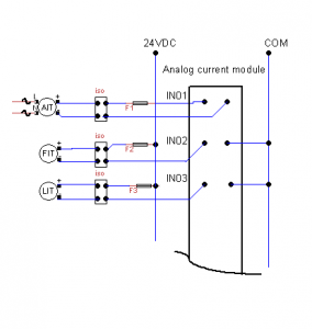
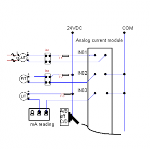
Here is a part of simplifying of PLC wiring diagram at a water treatment plant (see picture above). There are three transmitters that connect to a PLC analog current input module and with some reasons, they mysteriously failed to work at the same time at the same PLC module. Of course this event is rarely happened in real instrumentation field !. This example just to give idea what we are going to encounter in the field and how to solve these problems.
Most 4-20 signal generators or process meters sold in the market provide basic modes such as: source, simulate and to generate at least 24 Vdc for powering the loop. We will use our tool: 4inONE-4to20mA signal generator and a trainer in these examples.
A Cl2 Analyzer device powered by 110 VAC (AIT). The range was between 0 -10 mg/L(ppm). It showed 4.9 mg/L on device display itself but it showed 0 reading on SCADA monitor.
-> Check the analog output of Cl2 Analyzer. If the current reading shows approximately 12 mA, the problem should be somewhere else than the transmitter itself. Check the fuse and wire, make sure no blown fuse or broken loop. Open the loop, remove Isolator block (iso) and connect the probes in “SOURCE” mode like showing on the picture A. ON android app, set the source to “12” mA.
 Picture A.
If SCADA reading shows around 5 mg/L, the most likely failure come from Isolator block, otherwise we might have a faulty PLC analog current module.
A two-wires Flow Meter(FIT) which has range: 0-10 MGD indicated 8.75 MGD on its display but only showed 2.5 MGD on SCADA monitor.
->Let find both values in mA.
mA= (U/Ufs*16) +4
mA=reading in mA, U=reading in MGD , Ufs=Full scale of MGD
mA1=(2.5/10*16)+4 = 8 mA , mA2 =(8.75/10*16)+4 = 18 mA
To verify PLC input module that connect to two-wire transmitter, we need to connect the probes on “SIMULATE” mode like showed on picture B. Set android app to “18” mA. Make sure there is no blown fuse or broken loop. If SCADA monitor shows much less than 8.75 MGD, The problem might come from a bad PLC input module or PLC/SCADA scaling errors.
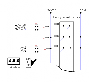 Picture B.
.A two-wires Level Transmitter (LIT) will shut down intermittently and will show erratic current readings.
-> Check Transmitter operation by connecting probes on “LOOP POWER” mode . (picture C). Monitor current reading on Android app.
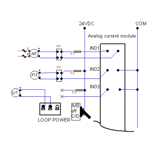 Picture C.
Replace Level Transmitter if the problem persists. If not continue to next step. Remove isolator and check existing 24 Vdc voltage. Using autographic and data logging on Android app, connect the probes like showed on picture D. Monitor current loop trending without isolator block installed.
 Picture D.
note:
AIT = Analytical Indicating Transmitter
FIT =Flow Indicating Transmitter
LIT =Level Indicating Transmitter
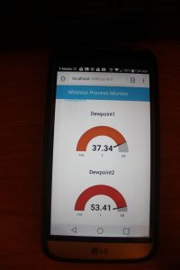
Read and write Allen Bradley tag values using python which utilize Common Industrial Protocol (CIP) on Ethernet/IP. This method will work on Controllogix and Compactlogix PLCs. The script will be executed in Node-red and the return value will be displayed on dashboard and can be read on wireless devices such as tablets or smartphones.
Requirements:
1.Raspberry pi 3 (Jessie).
2.Node-Red (It was already installed in latest Jessie but we might still need to get update to work with dashboard node).
3.Dashboard node. Here is the link to get this node:
4.python 2.6 or newer.
5.Python CIP library.
Get the library and code example from the following link:
If you follow on my previous article, you can switch Raspberry 3 pi to AP mode. Assign eth0 to static IP address. For example : wan address: 192.168.42.1
static eth0 IP address : 192.168.60.50
Connect PLC networks to Raspberry ethernet port. Make sure there is no conflict between Raspberry eth0 static address with gateway or PLC IP addresses. To access raspberry pi via tablets or smartphones you can use android app such as VNC viewer or ConnectBot. Alternatively you can also use VNC viewer or PuTTY on Windows version.
Use pylogix library to get a taglist and to read a tag value from PLC. Here is the example of python script to read “VLV_O3_HEADER_ISO_ZSC” tag from Controllogix PLC with IP address: 192.168.60.104.
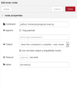
Start node-red. To get return value from python script, we need to put plcread.py on “EXEC” node.
Edit exec node:
Step 4.
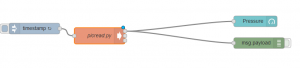
Build a flow.
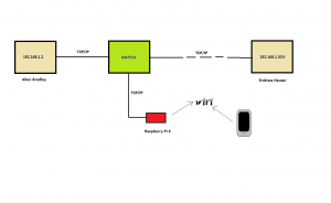
We can turn Raspberry pi 3 as AP(Access point) and can be utilized with wireless devices to scan PLCs or field devices network.
1.Raspberry pi 3
2.Power Supply (for Raspberry)
3.Wireless device ( tablet, laptop, or cellphone)
4.Ethernet cable
Keep in the mind that the following procedure is for Raspberry Pi 3 (Jessie raspbian) which I am quite sure it might work for some older versions with slightly modifications. I got the script from several sources online and I did modification to work on PLC network that use static IP addresses.
Basically this script is to create several configuration (conf) files and will load them into default ones. DHCP (Dynamic Host Configuration Protocol) configuration will give away the dynamic IP addresses between 192.168.42.2 and 192.168.42.20 to your wireless devices and to access wlan0 meanwhile it will give a static IP address for raspberry pi: 192.168.42.1 . For older version , it is necessary to setup configuration on /etc/network/interfaces for interfacing with network (wlan0,eth0, etc ) but on newest Jessie installation, the network configuration is located on /etc/dhcpcd.conf . HostAPD configuration will create hotspot and APN ( Access Point Name). The next is NAT (Network Address Translation ) which works as a translator between external router that connect to eth0 and WIFI guests who access wlan0. :
Run mywifi.sh and AP.sh
If there is no errors , you should able to see SSID name “WifiPLC” on your wireless devices under WIFI setting menu. Login and when ask the password, type “My_Passphrase” that will save and connect it to your wireless devices. To test it, connect eth0 (ethernet port) on Raspberry Pi to DHCP router that connect to Internet. The router will assign a dynamic IP address . Now you are able to connect to Internet. Type “www.google.com” on your phone browser to verify it.
This is last step if you need a static IP and skip it if you just need dynamic IP address . Eth0 still has a dynamic IP address and will not communicate with PLC static IP address network. Identify gateway address and check all existing PLC IP address and find a static IP address for Raspberry PI that will not cause conflicts with other numbers. In this example the gateway is 192.168.1.1 and the number has not been used by other PLCs is 192.168.1.50. To activate a static IP address, add the following to the very bottom of /etc/dhcpcd.conf file.
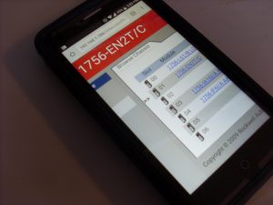
Reboot your Raspberry Pi , connect Ethernet port to a PLC router. Now if you have PLC CPUs or Ethernet modules which have “192.168.1.xx ” , type those number on your browser. Let says “192.168.1.33”. Most new Field devices or PLCs have HTTP protocol capability on port 80/8080, so you will see something like this :
Using Raspbian shell terminal, we can find MAC number using “arp’ command, install “nmap” utility to explore and troubleshoot the network such as scanning particular IP address blocks, checking open/closed ports etc.
Process or manufacturing plants have PLCs which get signal inputs from mechanical buttons, switches, limit switches and send signal outputs to activate relays, solenoid valves etc. In many cases, they use 24V DC power supply for PLC CPUs and their I/O modules. This voltage level is used for input modules and deliver 24VDC from output module to turn solenoid valves, coils etc.
For non-critical use and ignoring the latency , we can build simple 5V to 24V DC I/O adapter that can be used with our Microcontrollers to drive 24V DC rating relays and supplying switches/buttons.
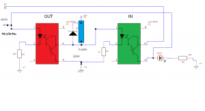
Don’t get confused with the schematic above . Yes, it works !. The reason there are two “opto couplers” above ( Actually only one opto coupler with two sockets which I will explain later) is that we can use GPIO from our Microcontrollers, AVRs, Arduino boards etc like we intended. For example we can use Pin 1 as input OR as output from the same block diagram above. Let says we have 8 I/O pins, each pin will go to both red and green block so we just need to focus on our code/program without worrying which one is for input or output.
HOW IT WORKS:
(See the picture) The main part here is 4N29 opto coupler that can “convert” either 5V DC to 24V DC or from 24V DC to 5V DC. The red square on the picture is a 4N29 socket for output ,and the green one is a socket for input. We have two sockets but we only need one opto coupler IC . When output signal needed , move this IC to the red socket, otherwise we just leave it on green socket. Never put two ICs on both sockets at same time to avoid input/output conflicts. The inputs/output devices will be connected to blue square terminal block. Put the relays, bulbs, solenoids, switches, and buttons there .
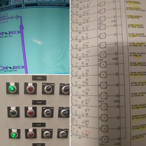
In the old days, We used to have electronic controllers or PLCs to send the warnings or alarms on the panel by turning combination of light indicators on or off. To understand these signals we have to refer their operation manuals to interpret these messages. For example if they have three indicators on the panel which has Light A(LA), Light B(LB) and Light C(LC), it will be 2^3 =8 combinations of warning/alarms. To make it easy to understand , they provide us a troubleshooting table to tell operators or technicians to trace the problem. Continue reading Convert legacy control panel into LCD alarm and warning system with Arduino.